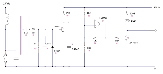
Processing the Original Points Signal for the ECU: -
| Date | Discussion |
|---|---|
| Feb 2023 |  The output signal taken from the distributor points is, electrically, very noisy. It contains significant, and completely spurious, spikes together with some very large voltage excursions caused by the characteristics of the ignitions coil. In a vehicle, the points simply do their job and the noise on the signal is irrelevant. However, if that same signal is also to be used to accurately and reliably drive a modern, computer controlled ECU, then it needs to be "cleaned up". It must have all the spurious portions of the signal removed which may otherwise confuse the fuel injector timing, and it must also have any voltage excursions over 5volts removed, since they would almost certainly damage the ECU. A lengthy search of the Internet found the circuit above, which has been modified somewhat, designed by Rob Mack, on a Discussion Forum dedicated to BMW twin motorcycles. Thanks Rob ! Circuit Description: - The existing distributor points signal goes to capacitor, C3, to remove the DC component. The signal is next fed to a 10:1 voltage divider consisting of R1/R2 which reduces the high voltage spikes. The capacitor R1/C4 forms a Low Pass filter to reduce the ringing characteristics of the signal. This becomes the input to an NPN transistor, T1. The diode D1 ensures that any negative going voltages are cut off at -0.7V and can't harm T1. The output on the collector of T1 is lengthened through an R-C time stretching circuit consisting of R3/C5 to about 2.5mS. The signal is now 5V p-p with a duration of about 1 mS - 2.5 mS, but it is unstable and rounded in shape. The second stage is a Schmitt trigger circuit comprised of a LM2904/LM358 dual general purpose op-amp, IC2, and resistors R4, R5 and R6. The Schmitt trigger provides a square wave output. The third stage of the circuit makes the signal compatible with the Arduino controller. The output needs to be negative going, so the Schmitt trigger is fed to an open-collector driver consisting of a single NPN transistor, T2 and resistor R7. This driver inverts the signal and protects the upstream circuitry from damage. The resistor R8 is a pull-up resistor and limits the current through the LED. When the transistor T2 is off, this resistor ensures that the output rises to 5volts, guaranteeing that the output voltage swing will be from 0V to 5V. The circuit was built on Veroboard and mounted in a small, separate, plastic box. The LED was included simply to provide a visual confirmation of signal activity. A screenshot from a dual band oscilloscope is included, in the photo gallery, showing the raw, incoming, signal and the resulting output ready for the ECU. The circuit really does perform very well. (Original design: - https://www.k100-forum.com/t12786-rpm-signal-conditioning-circuit-to-prevent-aftermarket-tachometer-needle-instability.) |

